#
360 Camera Pipeline
This document describes the step-by-step guidance for mapping with panorama cameras.
Pro or Enterprise license is required to use this feature.
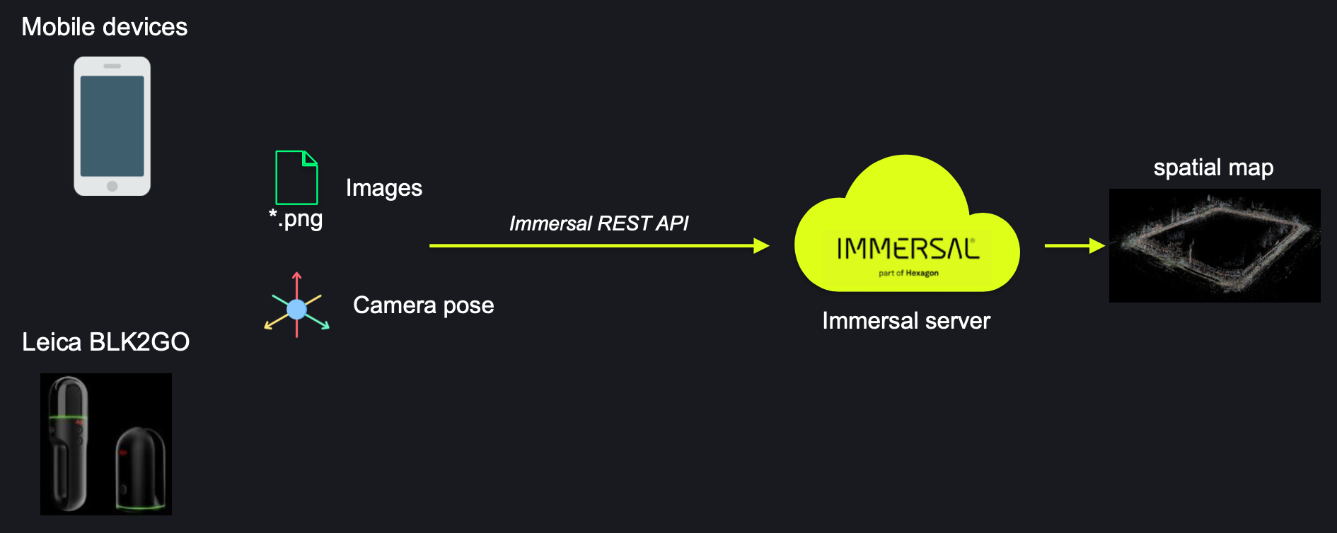
Immersal map construction requires two elements as input: images and camera pose. The mapping process with Phones/Tablets and BLK2GO is pretty simple (image 0.1), we can get both from your phone/tablet or BLK2GO. Specifically, the camera pose is from device's SLAM.
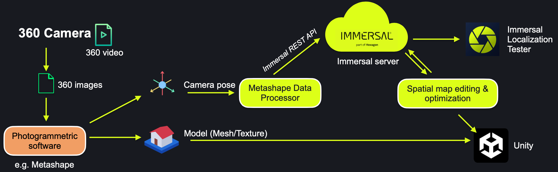
However, Panorama(360) camera doesn't have SLAM at all. The camera pose has to be estimated through Structure-from-Motion(SfM) approach. In practice, you may utilize 3rd-party photogrammetric software(e.g. Metashape) for that.
#
Tools
- Immersal developer account (Pro or Enterprise level)
- 360 camera, below are the recommended models: (06/2025)
- Insta 360 X5 (resolution 8k, good for both day-time and night-time)
- Insta 360 ONE RS 1-inch sensor edition (resolution 6.5k, good for low-light environment)
- Photogrammetric software, e.g. Metashape (Pro license needed).
- Scripts for converting and uploading to Immersal backend. We offer a sample script for Metashape.
- MeshLab (optional, for Map editing).
#
1. Mapping
#
1.1 Basic Principles
The primary principle for mapping is to ensure that the camera's position and orientation during mapping align with the expected pose where users will be localized. Hence, we must first determine the anticipated user location and the camera's front facing directional orientation for proper localization.
#
1.2 Route Planning (Urban Area)
In order to obtain the correct camera pose, we should plan the route during mapping, which must meet the following requirements:
- Ensure that the mapping route has a loop. The size of the loop should be determined according to the actual environment. For example, if we want to cover the streets in the right picture, a loop can be made for each block, and each loop should align with the others (i.e., ensure that the camera can capture overlapping frames).
- At the end, we need to return to the starting point.

Plan your route carefully
#
1.3 Route Planning (Open Area)
For open areas, such as squares, where there are no objects (e.g. buildings) surrounding it, we can walk freely. However, we still need to consider the basic principles, that is, we need to think about what routes the users might take for localization, where they might stop, and in what direction the camera should face. This will allow us to plan the best mapping route.
If there are some key objects or landscapes in the environment that need to be covered, such as a sculpture in the center square, we can do more mapping around it, but please note:
- Try not to rotate the camera, and it's best to keep the camera's orientation constant, otherwise, it might cause a jelly effect, affecting mapping.
- Ensure a uniform and slow walking speed, and do not suddenly stop or accelerate.

Mapping outdoor area
#
1.4. Mapping options
Users can choose to conduct the mapping through either taking panoramic photos or shooting panoramic videos. The former generally results in a spatial map of higher quality but is also more time-consuming and laborious. This is because photographs often achieve a higher resolution than videos and can avoid motion blur, ensuring the high quality of the images. Additionally, since users can freely control the shooting density, such as densely capturing key areas and sparsely capturing non-key areas, the final spatial map generated is usually smaller in size yet superior in quality compared to that derived from videos.
#
Option A: Taking 360 Photos
You can use a panoramic camera to capture panoramic images. You can hold the camera above your head and control the shooting using a mobile app (such as the Insta360 app). Generally, compared to recording videos, taking photos usually provides higher resolution and avoids motion blur. This method is recommended in extreme conditions (for example, in low-light environments like at night). However, it is more time-consuming and labor-intensive, because you need to take a photo every one or two steps. Depending on the size of your space, the entire mapping process may take several hours.
Tips
- Using a tripod ensures that the camera is stable during shooting. The photographer should ideally crouch down or stand slightly away from the camera and use a mobile device for control when taking photos. A photo should be taken at regular intervals, with the moving distance depending on the distance from the camera to the target object. A higher shooting density will be beneficial for mapping, but it will also result in a larger map file.
- Please do not conduct mapping during rainy or snowy weather.
- To support localization for all times, mapping should be conducted in every type of weather and at different times of the day, according to local weather conditions. For example, mapping can be done separately in the morning, afternoon (if there are significant differences on shadows), and evening. The same principle applies to different seasons.

#
Option B: Shooting 360 timelapse videos (Recommended) or normal video
Using a panoramic camera for mapping, the most efficient method is to record panoramic video. You can choose to record in either regular panoramic video mode or Timelapse mode—each has its own advantages.
- Timelapse mode (recommended): Before shooting, you can set the time interval between frames on the camera (for example, 0.5 seconds, 1 second, 2 seconds, or 5 seconds). The camera will then automatically capture an image at that interval. Compared to regular video mode, Timelapse mode has many benefits: you obtain higher-quality images (with higher resolution), the final video file is very small (making it easier to transfer), and you can record for long periods without worrying about the camera overheating and shutting down. The downside is that you cannot change the frame interval later.
- Normal mode: Recording panoramic video in normal mode is more flexible since you can adjust the frame interval during post-production (for example, one frame per second or one frame every five seconds). However, the image resolution is lower, the final video file may be very large, and recording for long periods in hot weather might cause the device to shut down automatically.
Tips
- Mount the 360 camera on a stick, extend the stick and hold it vertically above your head (at least one head's height above).
- Do not tilt it, or put it against your shoulder.
- Ensure the camera is well above head height; otherwise, if the photographer appears in the image occupying a large part, it may result in a significant amount of noise in the final map, which would affect the localization.
- During the mapping, the camera must be kept stable. Do not rotate the camera quickly or frequently (as this may lead to image blurring or a jelly effect), it is best to keep the angle constant. Moreover, do not adjust the camera's position during the mapping.
- Please maintain a uniform and slow speed, and avoid sudden acceleration, deceleration, or any significant motions. Moving too fast can cause image blurring, leading to parts of the map being missing.
- The mapping process should not be interrupted or paused (for example, you cannot stop to wipe the lens); it must be done in one go.
- Please do not conduct mapping during rainy or snowy weather.
To support localization for all times, mapping should be conducted in every type of weather and at different times of the day, according to local weather conditions. For Example, mapping can be done separately in the morning, afternoon (if there are significant differences on shadows), and evening. The same principle applies to different seasons.

#
2. Processing The Mapping Data
#
2.1. Processing Data: Photos
#
2.1.1 Importing 360 photos into Metashape
You may complete export 360 photos from the camera, then drag into Metashape.
#
2.2. Processing Data: Importing From Video
Export 360 video and prepare for importing to Photogrammetry software (e.g. Metashape)
You need to export the video from your camera as a panoramic flat view (equirectangular projection). Use a format that MetaShape can accept (mov, avi, fav, mp4, wmv). For Insta360 cameras, export the video through Insta360 Studio (desktop software). Make sure you are exporting 360 video, the encoding can be H.264 or ProRes(the file size will be a lot larger).


#
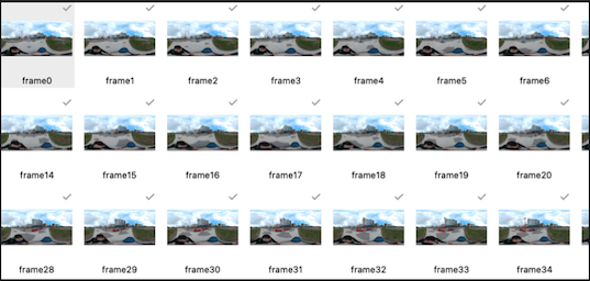
2.2.1 Frame Extraction:
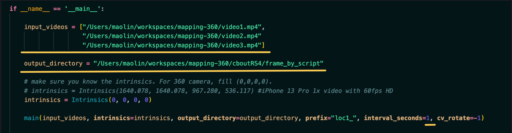
It is not recommended to use the frame extraction tool built into Metashape (as it may be uneven). You may do it yourself or use the sample frame extraction script we provide. Specify the input (which supports multiple videos), output directory and frame extraction interval (in seconds).

#
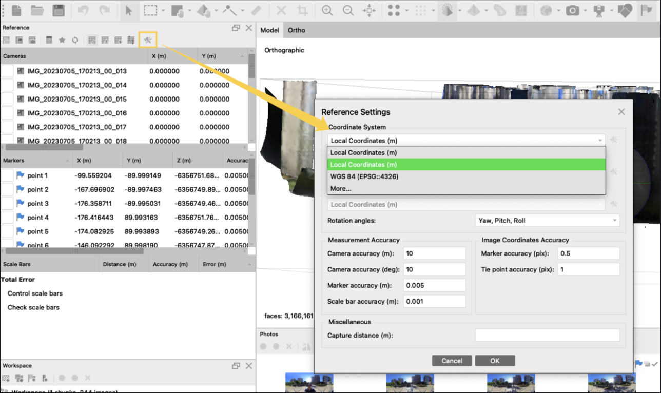
2.3. Setting the coordinate system:
The default might be WGS84 (latitude, longitude, altitude). Please make sure to switch to "Local coordinates" for 'x/y/z' representation allowing the coordinates to be represented in the 'x/y/z' format.
#
2.4. Aligning Photo to generate point-cloud
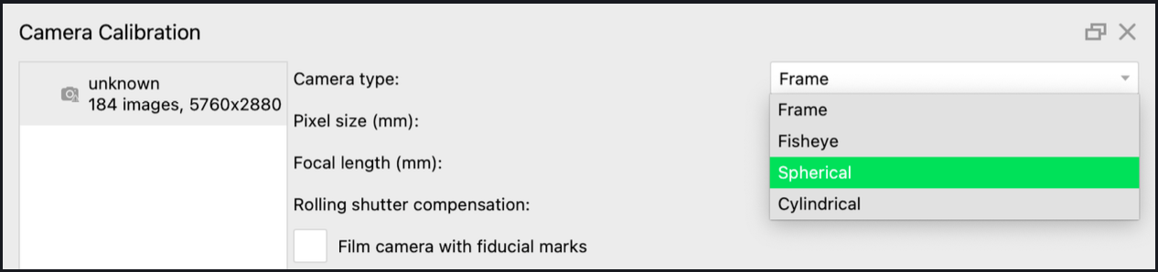
Click Tools -> Camera Calibration, Set Camera type as 'Spherical'
Then click Workflow -> Align Photos,select 'Accuracy'='Highest' and 'Reference preselection'='Estimated'. You may customize the 'key point limit' and 'tie point limit'. e.g. Increasing 'key point limit' would allow Metashape to extract more feature from the image, which could be beneficial for finding matches.

#
2.5. Generating Mesh and Texture
There are two purposes for generating Mesh and Texture:
- Having a mesh/texture would make it easy for us to add reference points/markers for fixing the scale.
- The mesh/texture can be later used in placing AR content to the space in Unity.
You may build mesh and texture by clicking:
- Workflow -> Build Mesh
- Workflow -> Build Texture

#
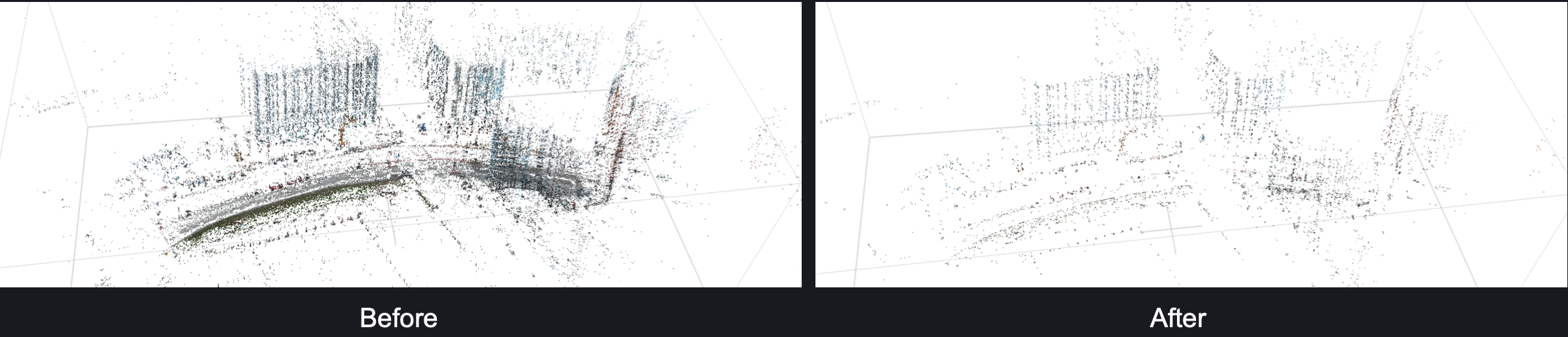
2.6. Checking the point-cloud and mesh
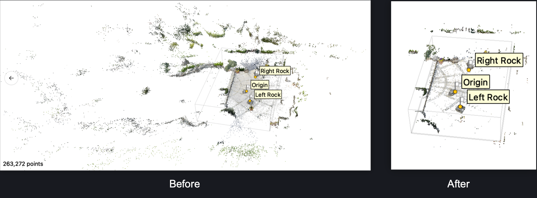
Please check the point-cloud and mesh! Look for any obvious errors. For example:
- Some areas are missing in the point-cloud. (as shown in the left image below)
- Misalignment, distortion, which do not match the physical space (as shown in the right image below)

Important Notes
In case there are errors as mentioned above, please realign photos.
- Try running 'Optimize camera', sometimes it can solve small problem.
- Try increasing the 'key point limit'
- Try re-execute 'Align map', sometimes after a few round, problem gets fixed.
If the problem still cannot be fixed within the software this usually indicates that the area was not properly mapped (due to lack of overlapping). Then you should consider going back on-site and re-map the problematic area, get more photo for that area then realign photos.
#
2.7. Fixing the scale and setting the coordinate system
The point cloud's default scale differs from the actual object scale. To fix the scale, we need to find some objects with known dimensions as references. We need to add at least 3 points (markers) in the point cloud. More is preferred to minimize the inaccuracy.
First, we need to find an object in the scene that is suitable as a reference. It is best if the object has right angles in the x, y, and z directions, which makes setting up the coordinate system easier. The larger the object, the better (in theory, a larger object reduces the probability of errors). For example, we might find a small house in the scene that meets these requirements.
At this point, we need to open (double-click) any photo that contains the object in Metashape, and add a reference marker by right-clicking → "Add Marker". Note that when a marker is added, Metashape will assign a default coordinate based on the current coordinate system. This coordinate is not accurate, so you can ignore it for now. You will then notice a small green flag on the photo, which indicates that a marker has been added and calibrated.

Now, when we open another nearby photo, we will notice that the reference marker's position deviates from where it should be (as indicated by the red circle in the figure). At this point, we need to drag the marker to adjust it to the correct position (you can zoom in to make a more precise adjustment). Once completed, you will see a small green flag on this photo as well, indicating that this image has also been calibrated.

We need to do the same for all nearby photos, ensuring that the reference marker is correctly positioned in every image that contains it. For each marker, we must calibrate its position as accurately as possible across all the images that include it. The more images we calibrate, the more precise the final scale will be.

Finally, we added four reference markers using the above method, each of which can be used to calibrate the scale in the x, y, and z directions. Now we need to measure the physical distance between each point. You can use a ruler, or you can use an app-based tool. For example, the "Measure" app on an iOS device with LiDAR is a great tool. Based on the measured values, we assign coordinates to these four points. It is important to note that we must use a right-handed coordinate system (not the left-handed system commonly used in Unity).

Then select all added reference points, and apply the new scale by clicking Model -> Transform Object -> Update Transform

#
Tips :
- It is best if you can find points in all the three axis (x, y and z), like seen in picture B, If it's not possible to find points in the vertical axis you may find several points in the horizontal plane as seen in picture A.
- In theory, to ensure the accuracy of the scale, the reference points we choose should ideally cover the entire space rather than just a small object within it. In other words, especially for maps with a large area, the greater the distance between the reference points, the better. If you can find such a grid in the scene, you only need to measure the edge length of a single grid cell. This allows you to cover a large area with reference points and calculate the coordinates for each one, which is a very effective approach.
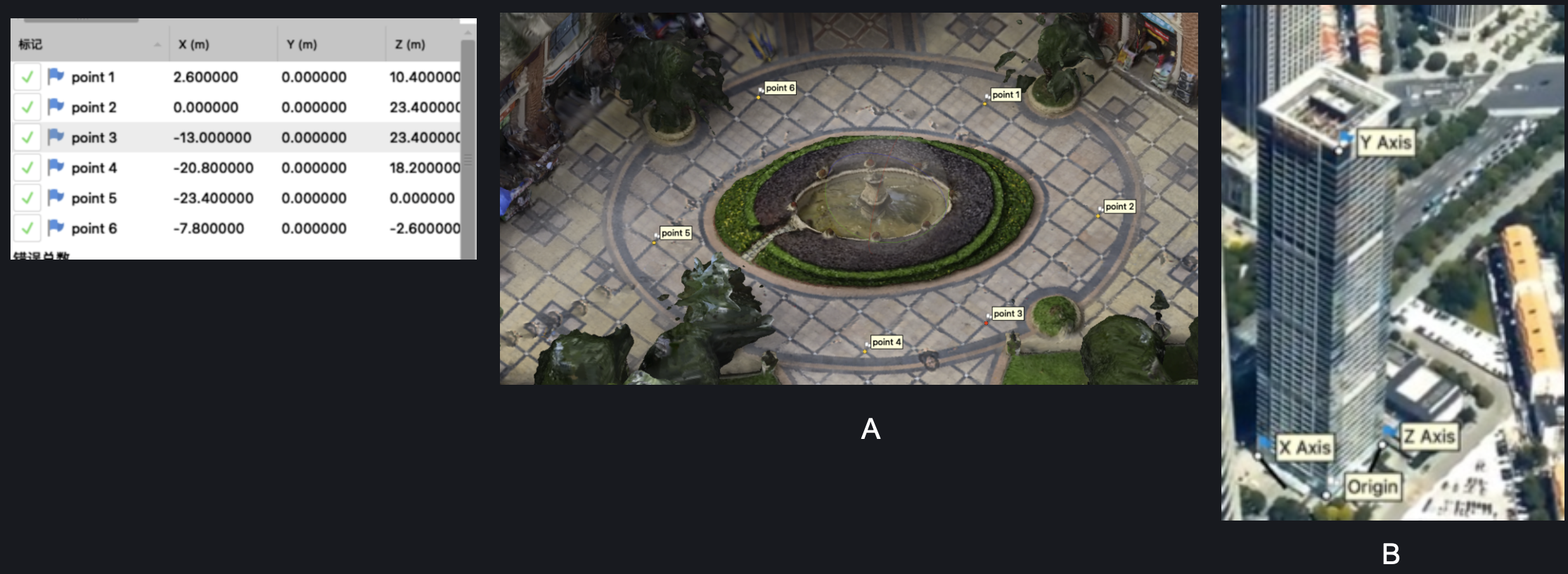
It is recommended to have markers in three (x/y/z) axis, and far away from each other
#
2.9. Optimize camera pose
Remove any unnecessary or incorrect points from the area. You can use the selection tool to select the points and then Delete (remove the selected points, retaining the others); or select the desired area, and then Crop (remove points outside the selected area, retaining the selected points).
Select Model -> Gradual Selection. Set the following parameters. For each selection, if there are any selected points, go to Edit -> Delete to delete the points, leaving only a very small number of points in the end.
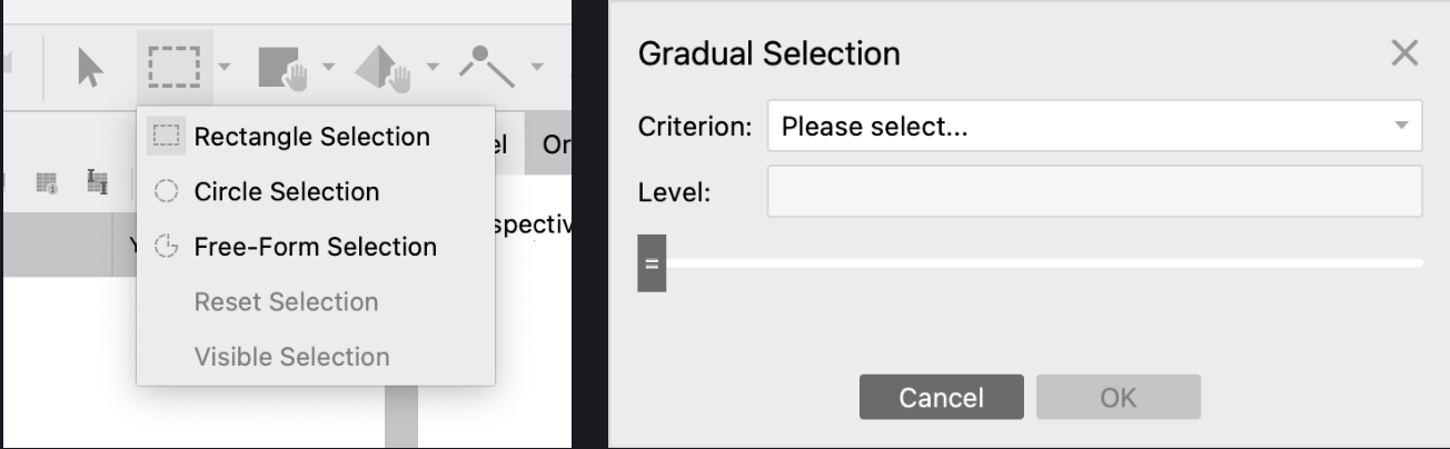
- Re-projection error: 0.5-1 (recommended: 1)
- Reconstruction uncertainty: 10-30 (recommended: 30)
- Projection accuracy: 3-5 (recommended: 3)
- Image count: 3-5 (recommended: 3)
When completed, click Tools -> Optimize Cameras
#
2.10. Export camera poses
Click File -> Export -> Cameras, then camera poses will be saved in XML format. - Save your project.
#
3. Converting data and start map construction
#
3.1. Convert the camera pose data
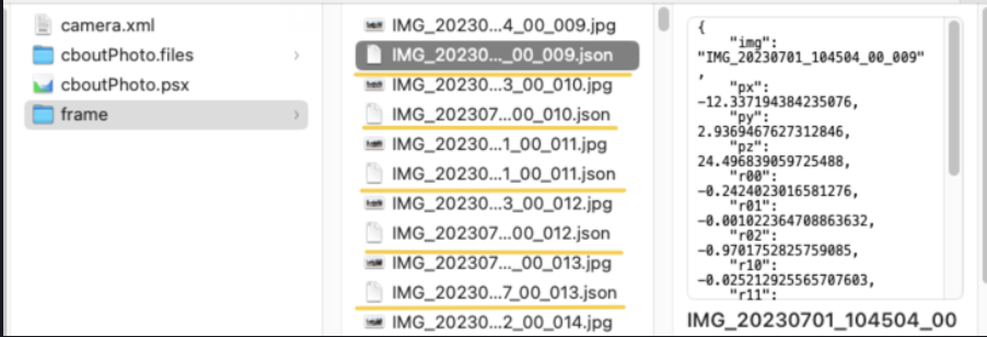
To be able to use the exported camera poses data, we must prepare it for each image. You may write your own script to convert the exported XML to json for each image. For Metashape, we provide a sample script metashape-xml-to-json.py for that purpose. To run it, you need to specify the path of exported XML file and the path of the images.
Once this step is completed, there will be a JSON file in the directory containing the photos, associated with each image, that includes its camera pose data.
#
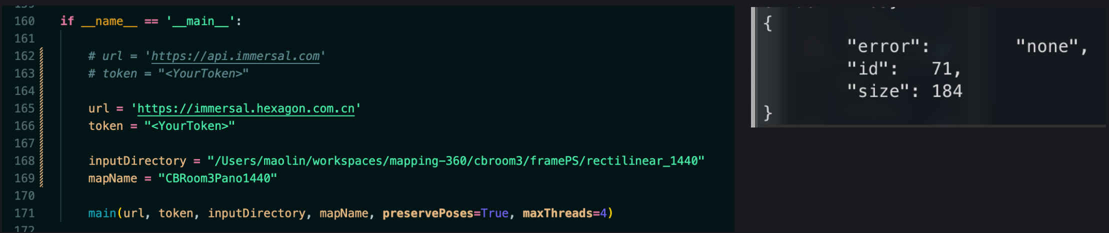
3.2. Submitting data to start map construction
Now you can use Immersal's processing script submit-images-and-json.py to upload the data to the Immersal server for map construction. Inside the script, you need to specify the URL of the Immersal server, your Immersal token, the map name, and the image directory. Please note that the map name must consist of letters or numbers (A-Z/a-z/0-9), and must not contain spaces or special characters (such as -, _, /, etc.).
Please pay special attention when there are many images; it is recommended to use a wired network for uploading (to prevent interruptions in the middle). If the console output shows "error": "none" at the end, it indicates a successful upload; otherwise, an error message will be printed.
#
4. Testing the map
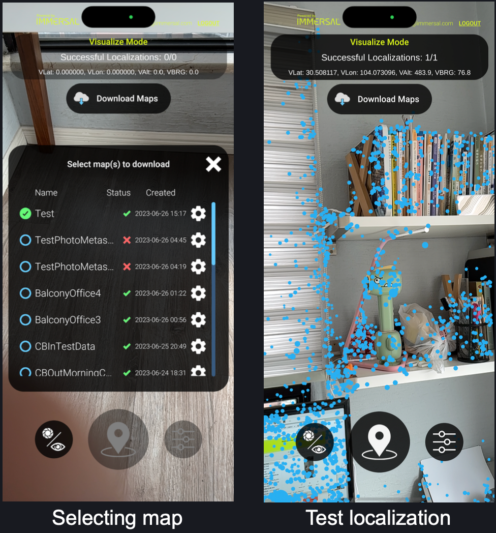
You can use the Immersal mapper app and test the location within the space.
#
5. Adding AR content
We can directly use the mesh/texture generated by Photogrammetry software to develop AR scenes.
- In Metashape, navigate to File -> Export -> Export Model and File -> Export -> Export Texture to export the model and texture.
- We can directly use the mesh/texture generated by Photogrammetry software to develop AR scenes.
- Please note that the default rotation of the model might be (-90, 0, 0), so you might need to reset it to (0, 0, 0).
- After that, you can start adding AR content. When you make the final build for your app, it's good practice to disable or delete the model.
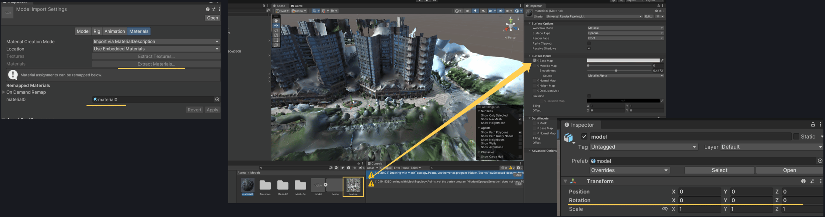
Correcting the pose of imported mesh
#
6. Editing and optimising the map (optional)
Panoramic cameras often capture extraneous objects, including the photographer themselves, trees, and so on. We can remove these unnecessary objects by manually editing the spatial map (point cloud), thereby increasing the success rate of positioning.
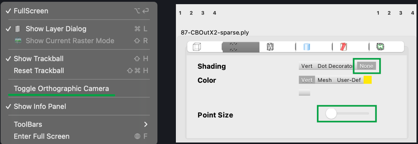
- Download the point cloud file with the suffix '-sparse.ply' from the Immersal developer portal, and open it with 3rd- party software 'MeshLab'.
- Within MeshLab, click View -> Toggle Orthographic Camera switch to an orthographic view, which is easier to observe the point cloud.
- In the point cloud information panel on the right, select None for Shading, to make the point cloud more visible. You may also manually adjust the Point Size for visibility.
You can download all scripts related to 360 pipeline from github here